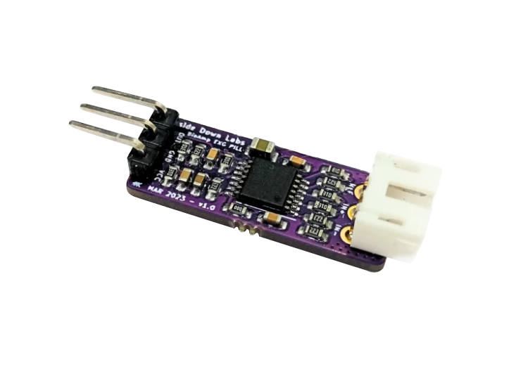
BioAmp EXG Pill#
v1.0
Overview#
BioAmp EXG Pill is a small, powerful analog-front-end (AFE) biopotential signal-acquisition board that can be paired with any microcontroller unit (MCU) or single-board computer (SBC) with an analog-to-digital converter (ADC) such as Arduino UNO & Nano, Adafruit QtPy, STM32 Blue Pill, BeagleBone Black, and Raspberry Pi Pico, to name just a few. It also works with any dedicated ADC, like the Texas Instruments ADS1115 and ADS131M0x, among others.
Note
It is recommended to use Arduino UNO R4 while recording biopotential signals since it has 14-bit ADC and can record the signals more accurately.
What makes it different?#
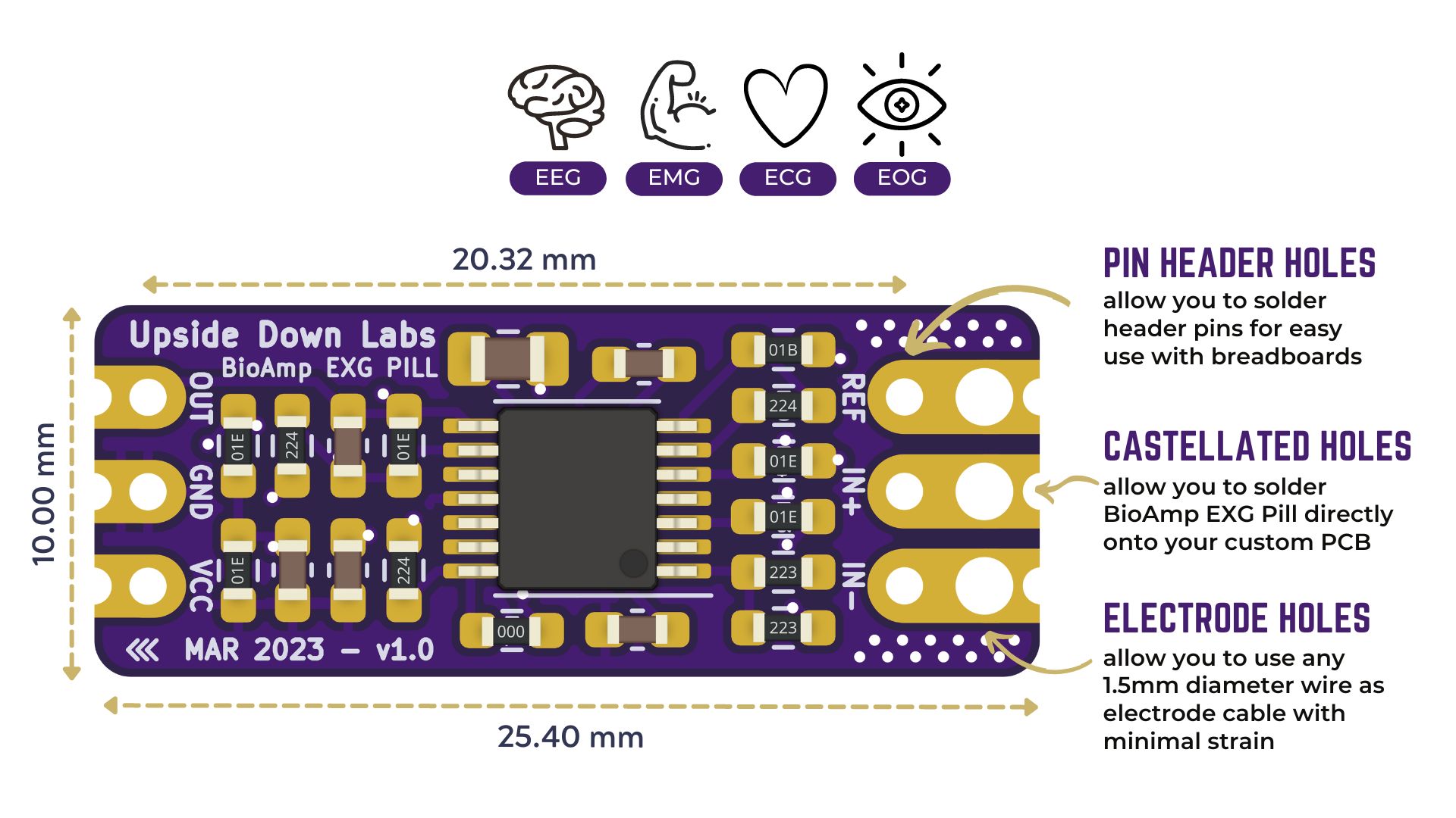
Record publication-quality biopotential signals like ECG, EMG, EOG, or EEG.
Small size (25.4 x 10.0mm) allows easy integration into mobile and space-constrained projects.
Powerful noise rejection makes it usable even when the device is close to the AC mains supply.
Any 1.5 mm diameter wire can be used as a strain-relieving electrode cable, making it very cost-effective.
Configure the gain, band pass filter and electrode count according to your requirements.
Features & Specifications#
Operating Voltage |
3.3/5 V |
Input Impedance |
10^12 ohm |
Compatible Hardware |
Any development board with an ADC (Arduino UNO & Nano, Adafruit QtPy, STM32 Blue Pill, BeagleBone Black, Raspberry Pi Pico, to name just a few) or any standalone ADC of your choice |
BioPotentials |
EMG, ECG, EOG, EEG (configurable band-pass, by default configured for EEG & EOG) |
No. of channels |
1 |
Electrodes |
2 or 3 (By default configured for 3 electrodes) |
Dimensions |
25.4 x 10 mm |
Open Source |
Hardware + Software |
Board layout#
BioAmp EXG Pill’s elegant design allows it to be used in 3 ways:
Pin-header holes allow you to solder (berg strip) pin headers for easy use with a breadboard.
Castellated holes allow you to solder BioAmp EXG Pill directly onto a custom PCB that requires biopotential-amplification capabilities.
Electrode holes allow you to use any 1.5 mm diameter wire as an electrode cable with minimal strain.
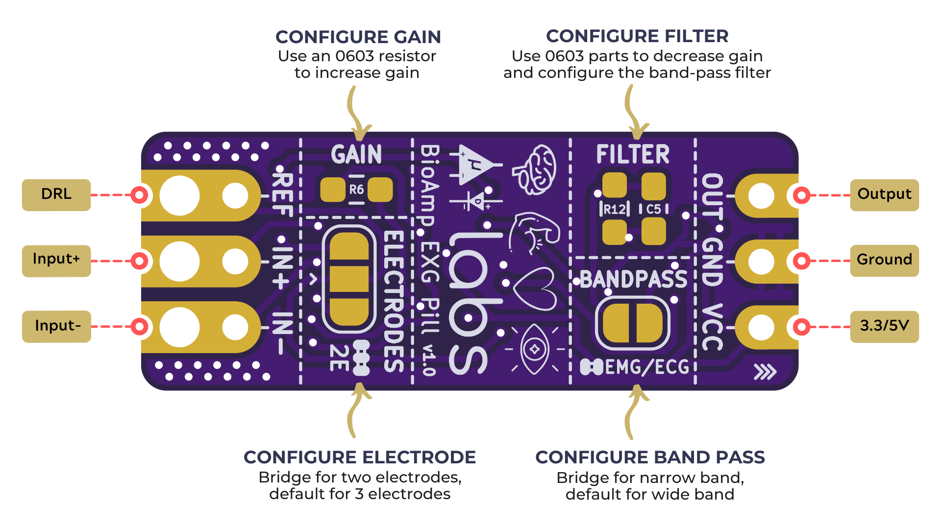
BioAmp EXG Pill is fully configurable#
BioAmp EXG Pill is optimised to record all your biopotential signals (EMG/ECG/EOG/EEG) accurately thus it is not recommended to change its gain. But in case you want to do so, use a 0603 resistor at
R6. Decrease gain and configure the bandpass filter by using 0603 parts atR12andC5. Band limiting is very useful for EOG and EEG recording. Also, the signal sometimes clips while recording an ECG with electrodes very close to the heart. Creating a solder jumper for a band-pass filter helps with that. By default, BioAmp EXG Pill is configured to record EEG and EOG but you can bridge the pads (below bandpass) with solder to make it configurable for EMG and ECG.The normal method of operation for best-quality signal amplification is to use 3 electrodes by default but you can bridge the pads (below electrodes) to make it configurable for 2 electrodes. The 2-electrode mode is specifically included for projects like heart (ECG) patches for HRV. It’s only supposed to be used with a battery-operated setup and is quite prone to high interference noise due to a lack of proper reference on the body (This option is not recommended for most operations)
Software requirements#
To use BioAmp EXG Pill, you will need the softwares mentioned below. Instructions on how to use them are provided later in the guide.
Arduino IDE (Download this to upload Chords arduino firmware to your development board)
Chords Web (Use this open-source web application to visualize your biopotential signals)
Visual Studio Code (or any other Code editor of your choice)
Python (To run Chords-Python script)
Chords Python (Use this open-source python script designed to record and visualize biopotential signals)
Note
The Chords Arduino firmware is identical for both Chords Web and Chords Python, so you only need to upload the code once, and you’re all set.
You can choose either Chords Web or Chords Python to record and visualize your biopotential signals based on your needs. If you’re curious, you can try both one at a time.
Using the Hardware#
If you have received the assembled BioAmp EXG Pill then you can skip the step 1 and move on to step 2.
Step 1: Solder Connectors#
Insert the provided BioAmp cable’s JST PH connector and header pins from top as shown in the image and solder them from below.
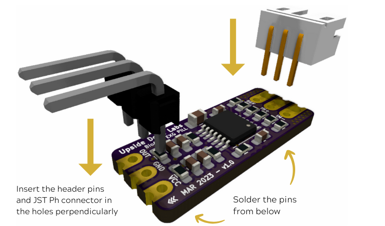
Soldering the connector & header pins on BioAmp EXG Pill#
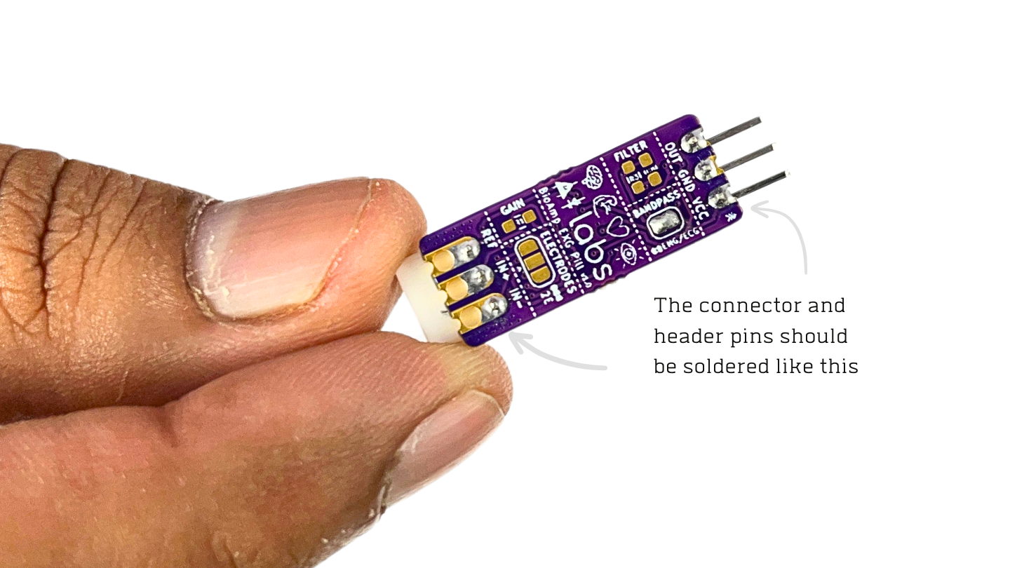
After soldering, BioAmp EXG Pill should look like this#
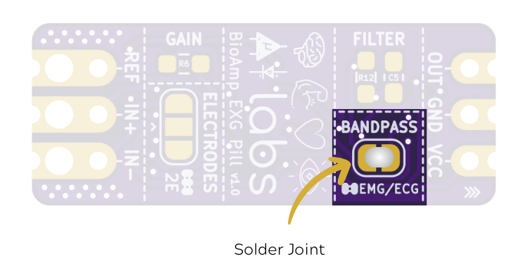
Step 2 (optional): Configure for ECG/EMG#
BioAmp EXG Pill is by default configured for recording EEG or EOG but if you want to record good quality ECG or EMG, then it is recommended to configure it by making a solder joint as shown in the image.
Note
Even without making the solder joint the BioAmp EXG Pill is capable of recording ECG or EMG but the signals would be more accurate if you configure it.
Step 3: Connect MCU/ADC#
Connect your BioAmp EXG Pill to your MCU/ADC as per the connection table shown below:
BioAmp |
MCU/ADC |
|---|---|
VCC |
3.3/5V |
GND |
GND |
OUT |
ADC Input |
If you are connecting OUT pin of BioAmp to any other analog pin of your development board, then you will have to change the INPUT PIN in the Arduino sketch accordingly.
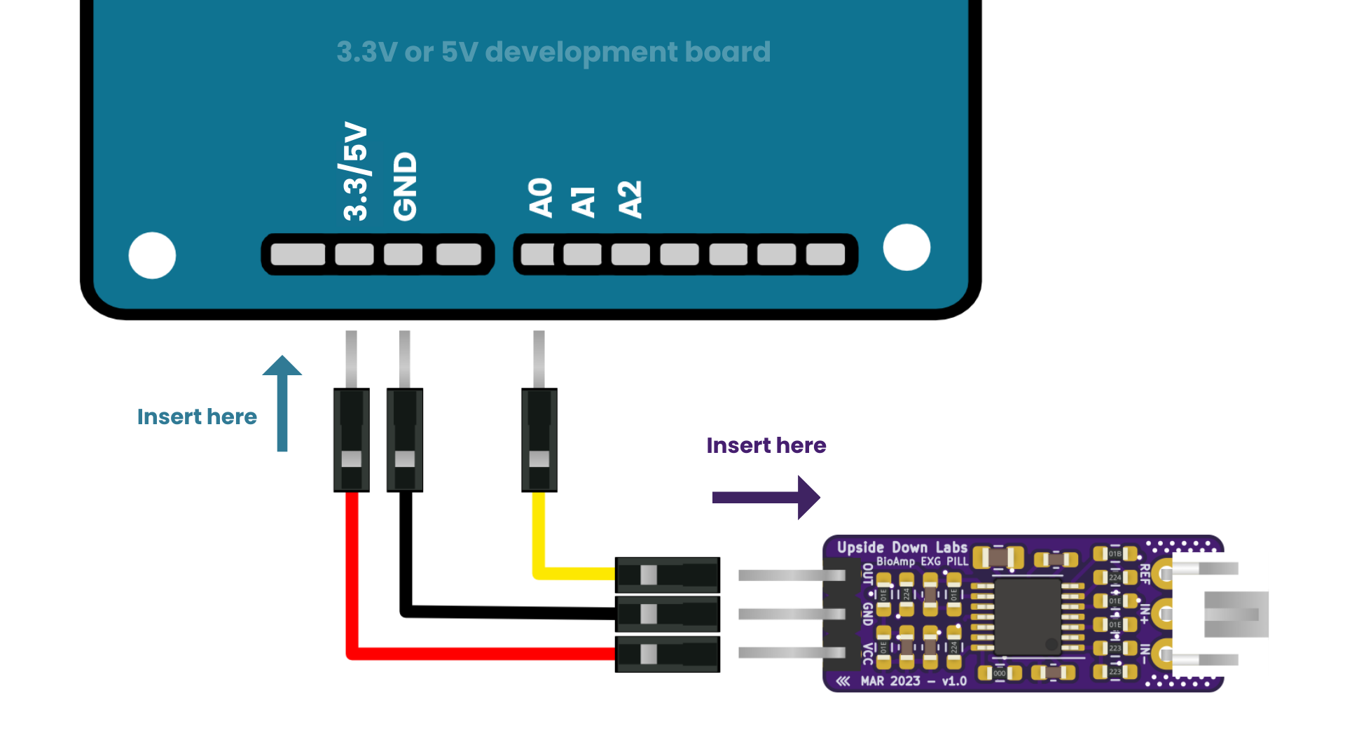
Connections with 3.3/5V development board#
Warning
Take precautions while connecting to power, if power pins (VCC/GND) are to be swapped, your BioAmp EXG Pill will be fried and it’ll become unusable (DIE).
Step 4: Connecting electrode cable#
Connect the BioAmp cable to BioAmp EXG Pill by inserting the cable end in the JST PH connector as shown in the graphic below.
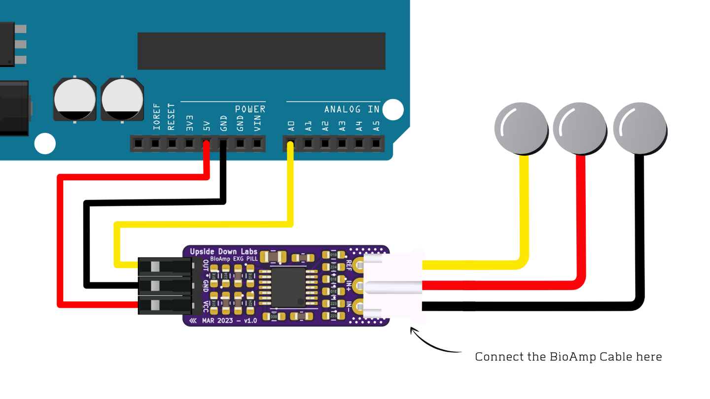
Connections with BioAmp Cable v3#
Step 5: Skin Preparation#
Determine the target area and apply Nuprep Skin Preparation Gel on the skin surface where electrodes would be placed to remove dead skin cells and clean the skin from dirt. After rubbing the skin surface thoroughly, clean it with an alcohol wipe or a wet wipe.
For more information, please check out detailed step by step Skin Preparation Guide.
Step 5: Electrode placement#
We have 2 options to measure the signals, either using the gel electrodes or using dry electrode based BioAmp Bands. You can try both of them one by one.
Once you have made the connections, return here to proceed to the next steps.
Step 6: Uploading the code#
Connect the development board to your laptop using it’s USB cable. Go to Chords Arduino Firmware github repository, scroll down to see a list of development boards compatible with Chords Software Suite. Copy the arduino sketch corresponding to your development board and paste it in Arduino IDE that you downloaded earlier.
Link for the Github repo: Chords Arduino Firmware
If you are using Arduino UNO R3/Arduino Nano/Arduino Mega/Maker Uno, you will have to uncomment the corresponding macro (eg. uncomment
#define BOARD_MAKER_UNOwhen using Maker Uno) at the start of the code.If you are using any other development board then skip step 2.
Now go to
tools>boardand select you board name. If the name doesn’t appear, install the required libraries. In the same menu, select the COM port on which your board is connected. To find out the right COM port, disconnect your board and reopen the menu. The entry that disappears should be the right COM port. Now click on the upload button.
Warning
Make sure your laptop is not connected to a charger and sit 5m away from any AC appliances for best signal acquisition.
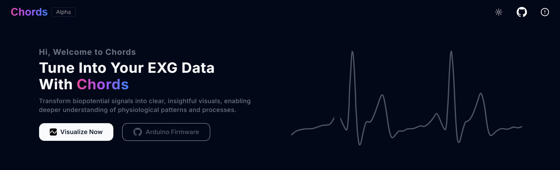
Step 7: Setting up Chords Web#
Visit chords.upsidedownlabs.tech.
Click on “Visualize now” button.
- At the bottom, you can see buttons to access various applications:
Chords Visualizer: Use this application for real-time data visualization, recording and data management, filter options, and multi-channel support.
FFT Visualizer: Use this app to visualize filtered EEG signals in real-time, FFT graph, EEG frequency bands, and a beta candle to determine your focus.
Serial Wizard: This interface provides real-time serial data visualization using serial plotter and monitor, optimised data rendering, baud rate selection and options to toggle between different modes.
Click on any of the button according to your requirement, select the COM port and click OK. You will be able to visualize your signals on the screen.
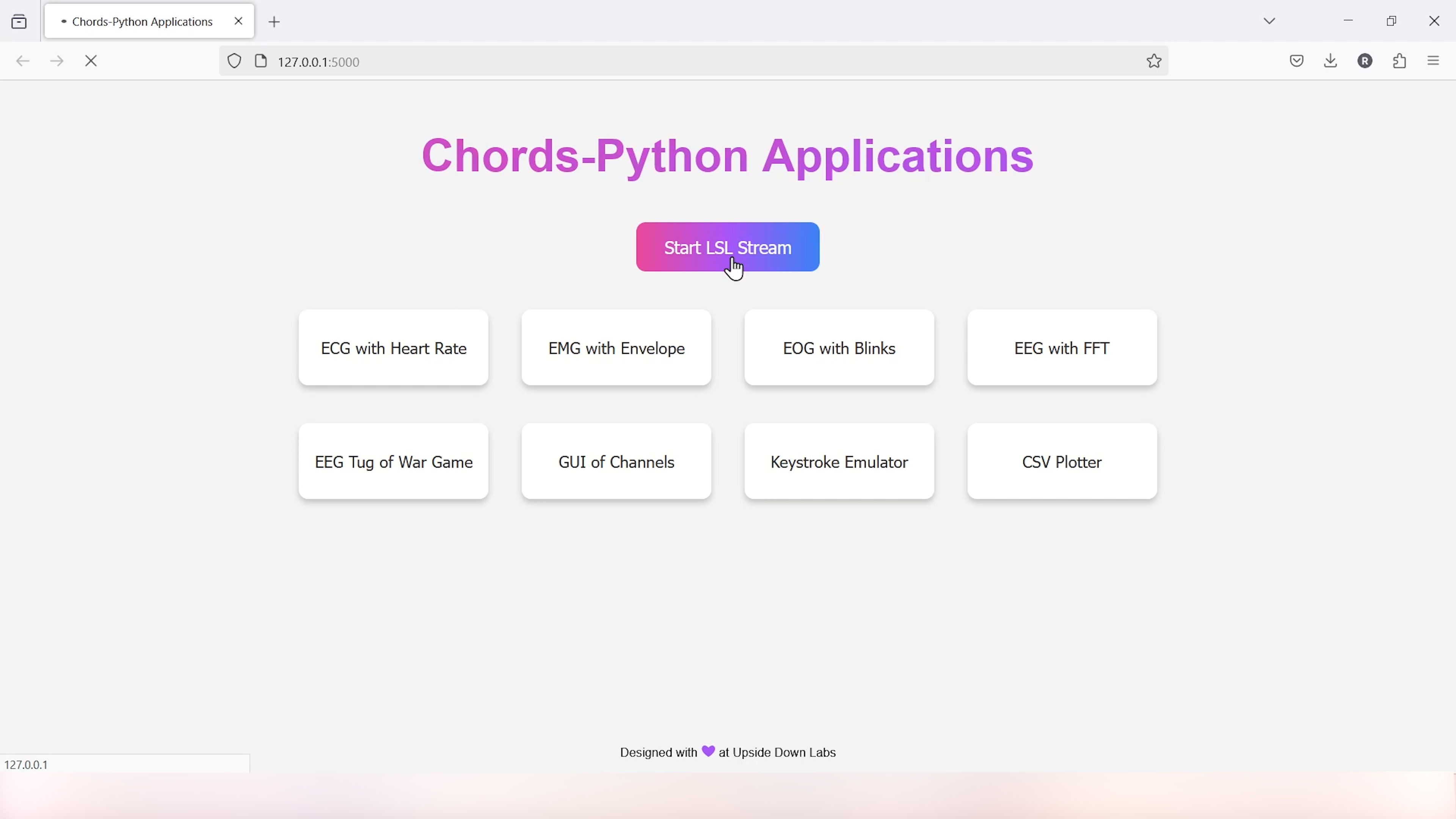
Step 8: Setting up Chords Python#
Since you have uploaded the firmware already to your board, use our python script and follow the steps given in the Chords-Python documentation for LSL streaming, CSV data logging, verbose output with detailed statistics and error reporting. Not only that, you get a complete web interface to access various applications (like ECG with heart rate, EMG with envelope, GUI of channels, CSV plotter, etc.) that you can use to further analyse your signals and create HCI/BCI projects.
Glimpses of previous versions#
The BioAmp EXG Pill can be used in a variety of ways, the YouTube video below shows a potential way of using v0.7 of
BioAmp EXG Pill.
A lot has improved in terms of interference rejection and flexibility from v0.7 to v1.0 of the BioAmp EXG Pill. The YouTube video
below shows the ECG, EMG, EOG, and EEG recording using v1.0b of device.
Real-world Applications#
BioAmp EXG Pill is perfect for researchers, makers, and hobbyists looking for novel ways to sample biopotential data. It can be used for a wide variety of interesting biosensing projects, including:
AI-assisted detection of congestive heart failure using CNN (ECG)
Heart-rate variability calculation to detect heart ailments (ECG)
Prosthetic arm (servo) control (EMG)
Controlling a 3DOF robotic arm (EMG)
Real-time game controllers (EOG)
Blink detection (EOG)
Capturing photos with a blink of an eye (EOG) and many more examples.
Project ideas & tutorials#
Projects on Instructables
Below are some projects made by students using the BioAmp EXG Pill.
These are some of the project ideas but the possibilities are endless. So create your own Human Computer Interface (HCI) and Brain Computer Interface (BCI) projects and share them with us at contact@upsidedownlabs.tech.