Muscle BioAmp Shield#
v0.3
Overview#
Muscle BioAmp Shield is an all-in-one Arduino Uno ElectroMyography (EMG) shield for learning neuroscience with ease which is inspired from BackYard Brains (BYB) Muscle Spiker shield and provides similar features like hobby servo output, user buttons, LED Bar, Audio output, and battery input. It is perfect for beginners as they can easily stack it on top of Arduino Uno to record, visualize and listen to their muscle signals to make amazing projects in the domain of Human-Computer Interface (HCI).
Features & Specifications#
Muscle BioAmp Shield comes with various plug-and-play options so you can connect hundreds of extension boards like OLED screens, character displays, accelerometers, and servo controllers to name just a few using the STEMMA I2C interface. You also get STEMMA digital and STEMMA analog ports. On STEMMA analog port you can connect additional BioAmp EXG Pill or any other sensor with analog output. On STEMMA digital port you can connect any digital sensor or actuator of your choice.
Input Voltage |
5V |
Input Impedance |
10^11 ohm |
Fixed Gain |
x2420 |
Bandpass filter |
72 – 720 Hz |
Compatible Hardware |
Arduino UNO |
BioPotentials |
EMG (Electromyography) |
No. of channels |
1 |
Electrodes |
3 (Positive, Negative, and Reference) |
Dimensions |
6.0 x 5.3 cm |
Open Source |
Hardware + Software |
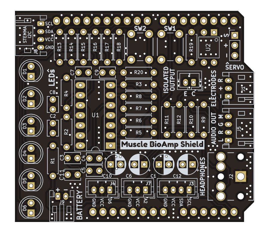
Hardware#
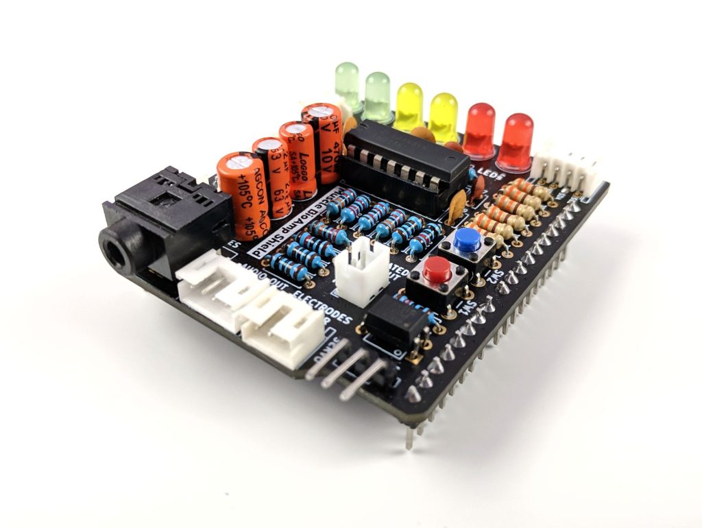
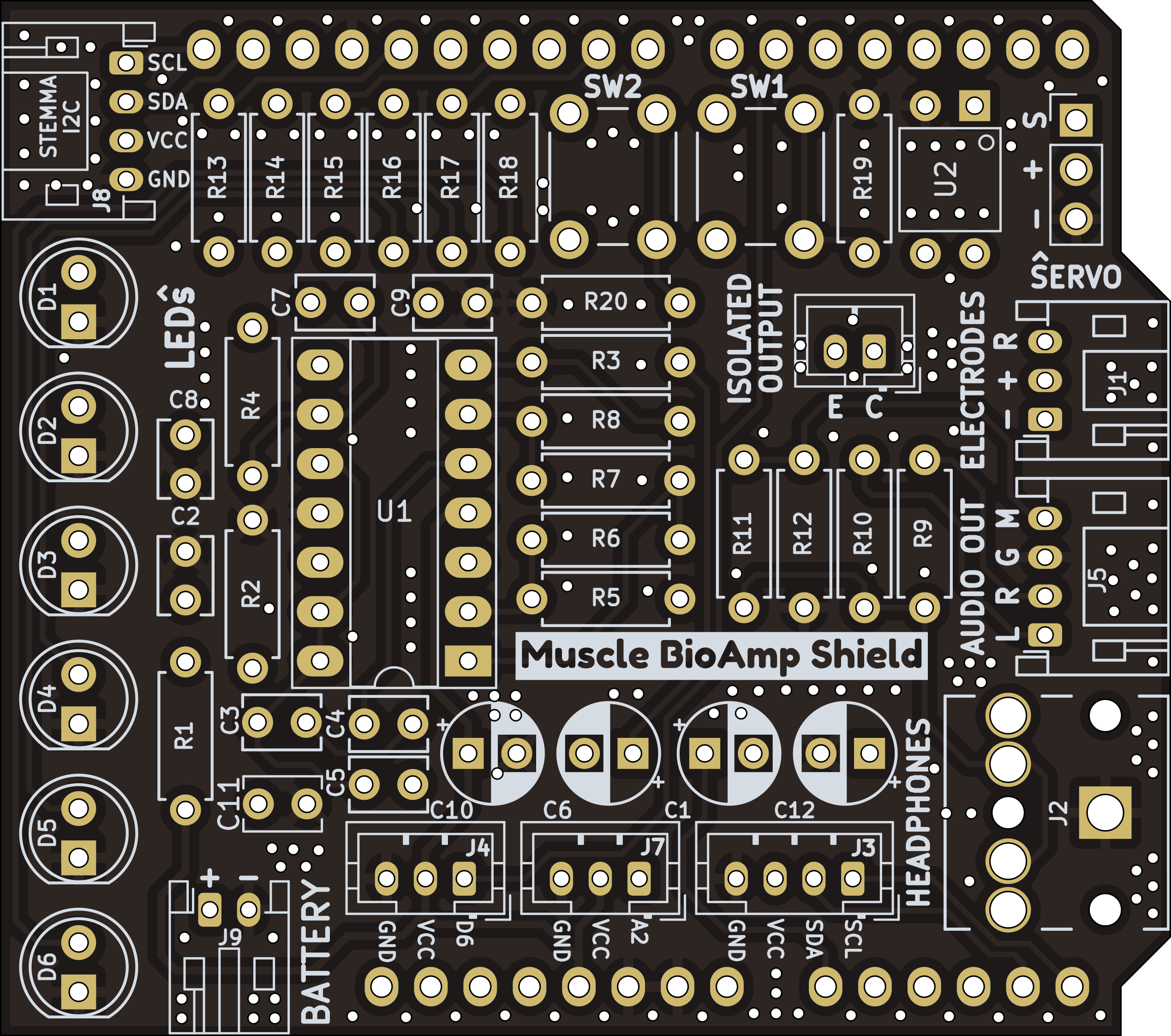
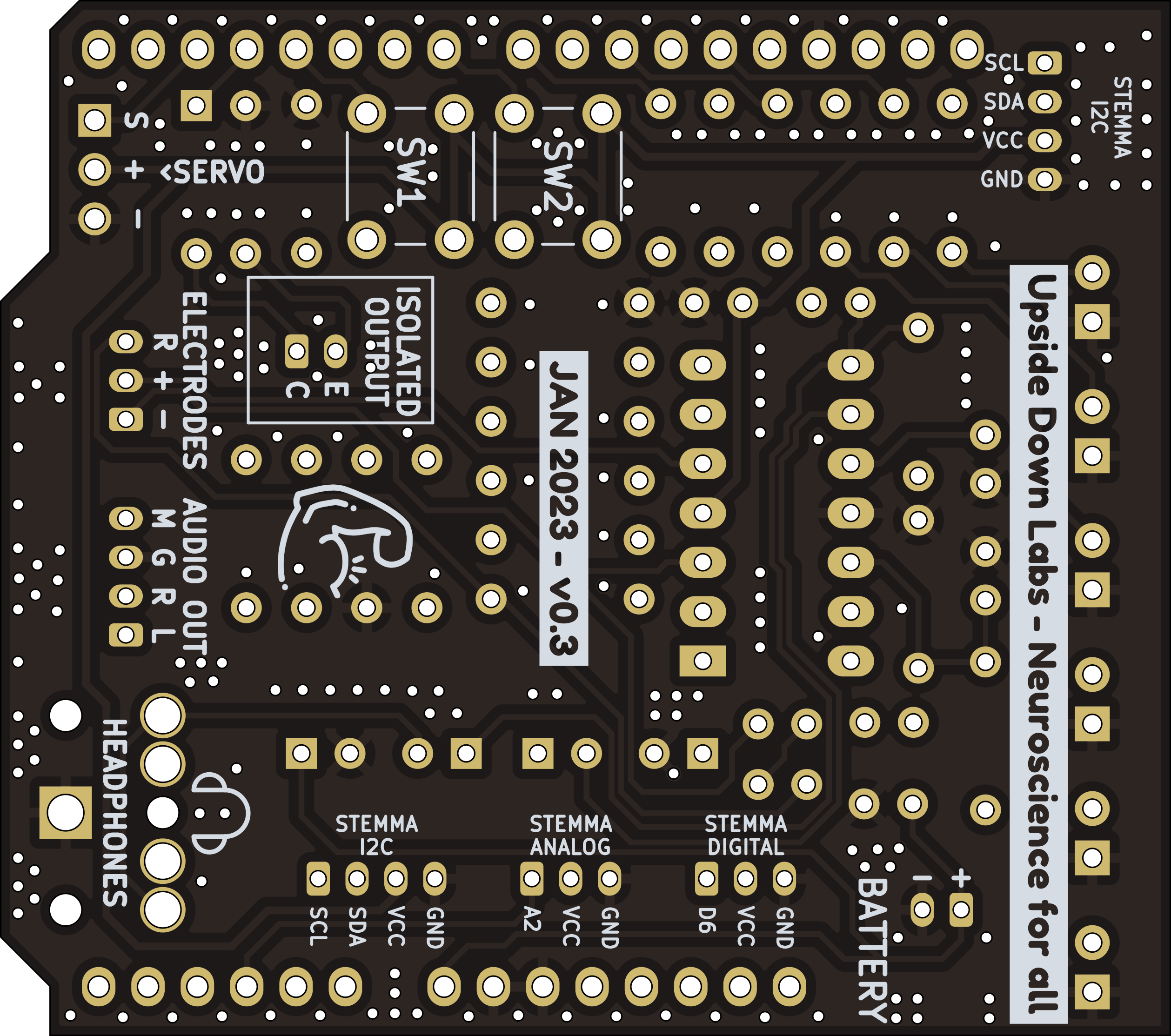
Images below shows a quick overview of the hardware design.
PCB Front
PCB Back
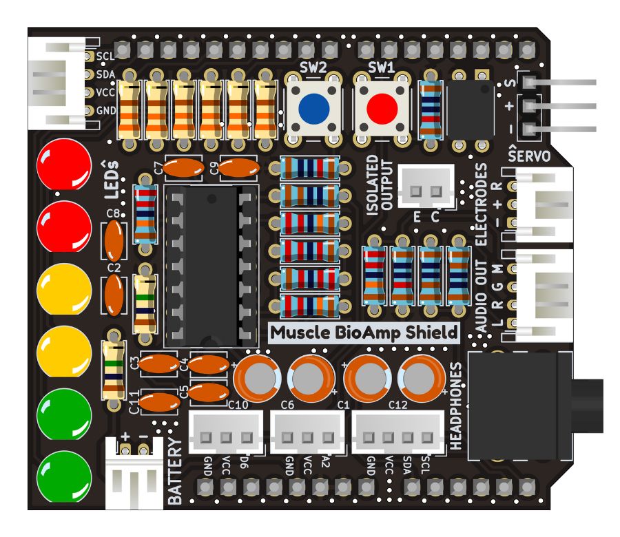
Assembled PCB#

PCB Layout#
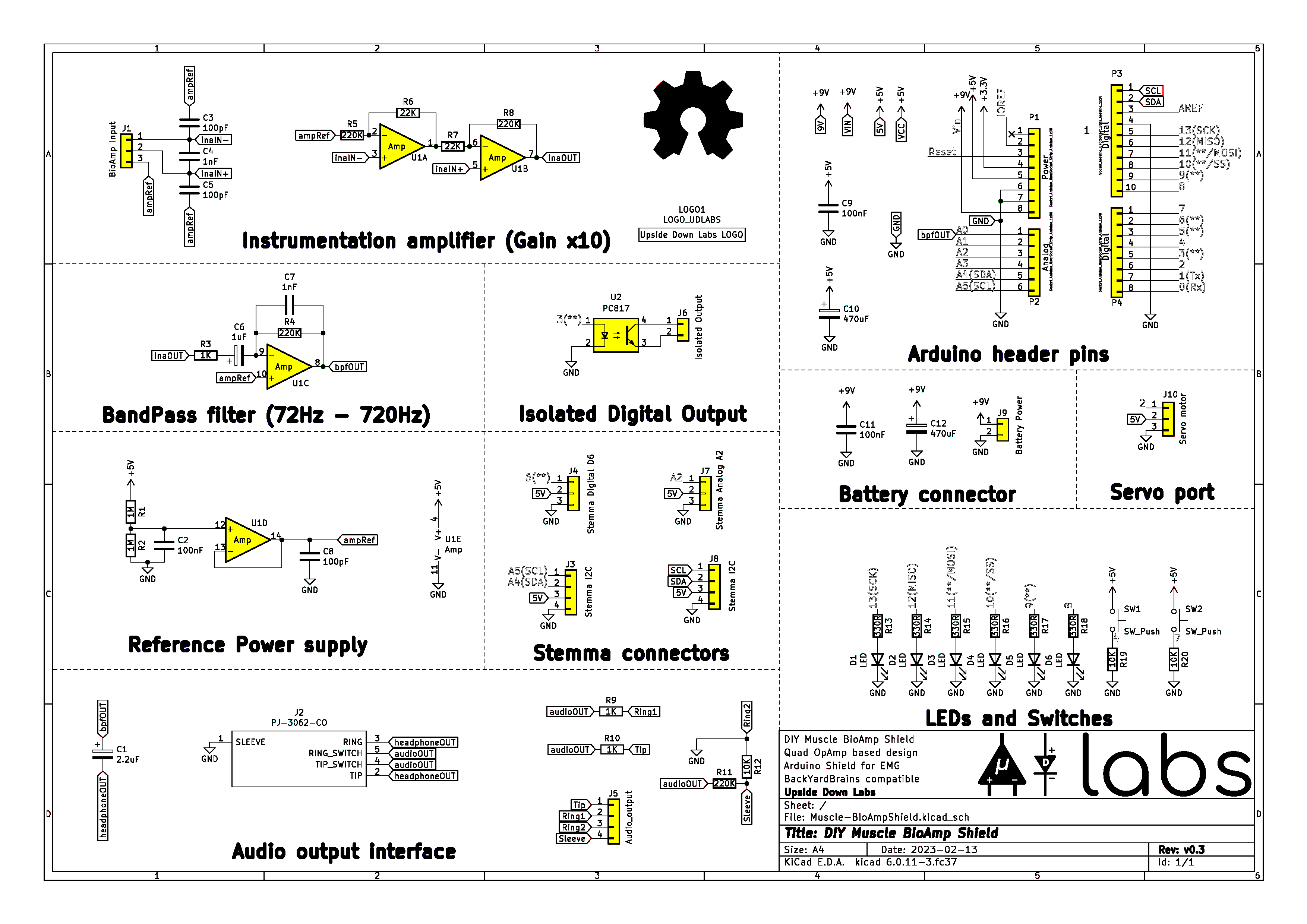
Schematic Diagram#
Contents of the kit#
There are 2 variants available for Muscle BioAmp Shield v0.3 kit - one comes with the shield assembled and the other one contains bare PCB of the sensor and the components separately which you can assemble pretty easily.
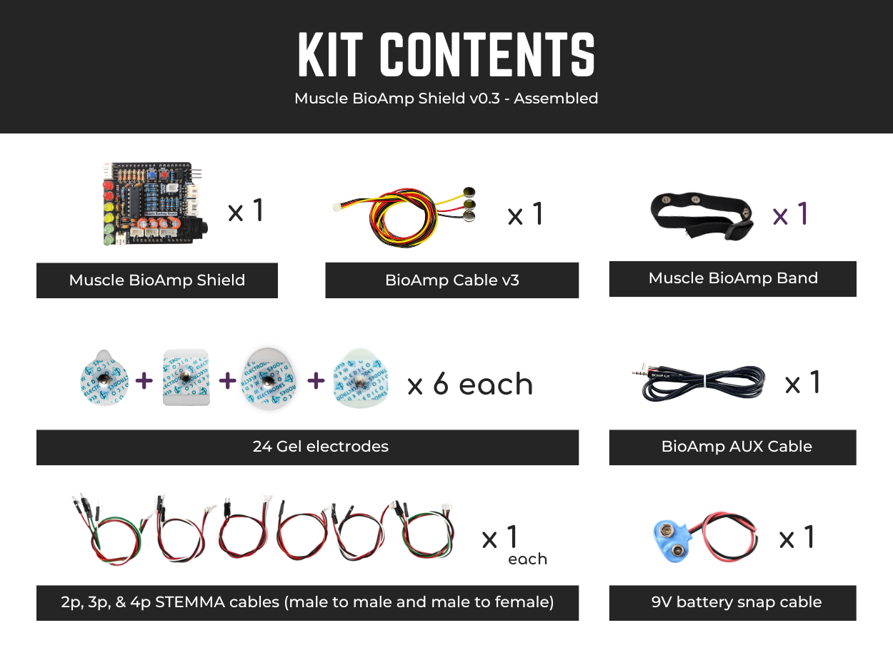
Assembled Muscle BioAmp Shield kit content#
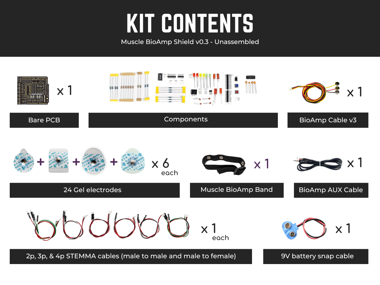
Unassembled Muscle BioAmp Shield kit content#
Click on the link below to see the unboxing of the kit:
Software requirements#
To use Muscle BioAmp Shield, you will need the softwares mentioned below. Instructions on how to use them are provided later in the guide.
Arduino IDE (Download this to upload Chords arduino firmware to your development board)
Chords Web (Use this open-source web application to visualize your biopotential signals)
Visual Studio Code (or any other Code editor of your choice)
Python (To run Chords-Python script)
Chords Python (Use this open-source python script designed to record and visualize biopotential signals)
Note
The Chords Arduino firmware is identical for both Chords Web and Chords Python, so you only need to upload the code once, and you’re all set.
You can choose either Chords Web or Chords Python to record and visualize your biopotential signals based on your needs. If you’re curious, you can try both one at a time.
Assembling the Kit#
You can get your own Muscle BioAmp Shield bag of parts from our online stores (shipping worldwide) and for assembling your shield you can take a look at this interactive BOM or the step by step guide below.
Note
Follow the highlighted yellow shapes to assemble your shield!
Step 1 - Bare Board#
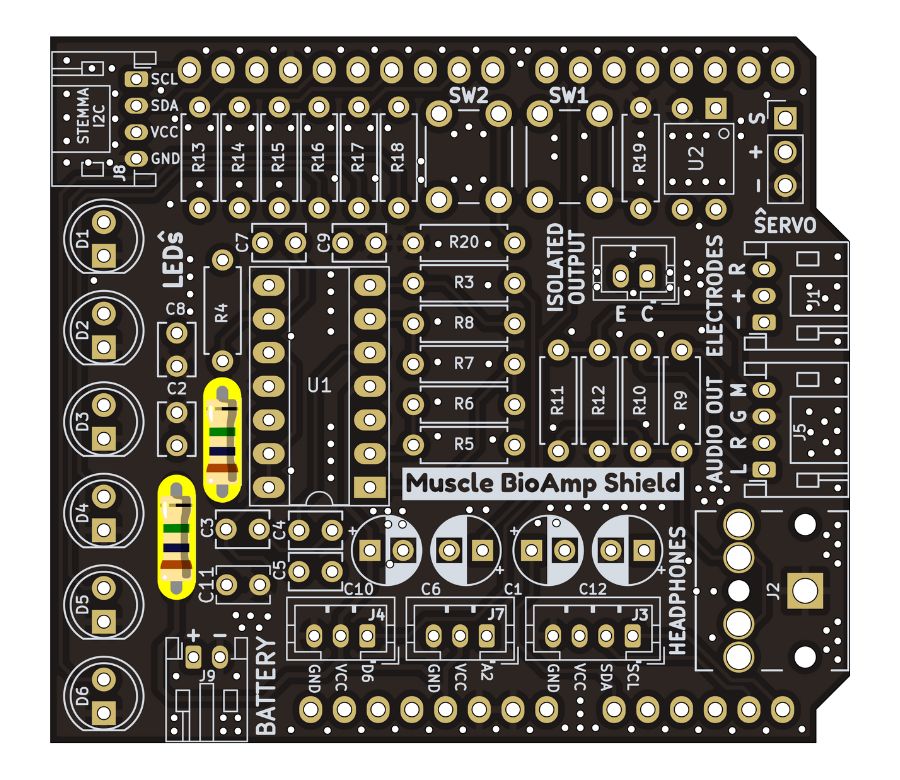
Step 2 - 1M Resistors#
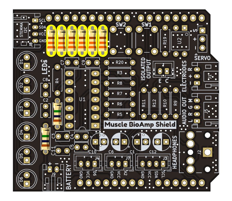
Step 3 - 330R Resistors#
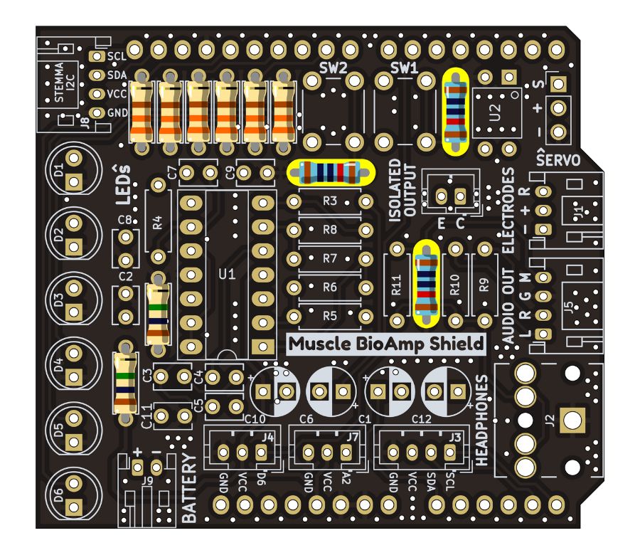
Step 4 - 10K Resistors#
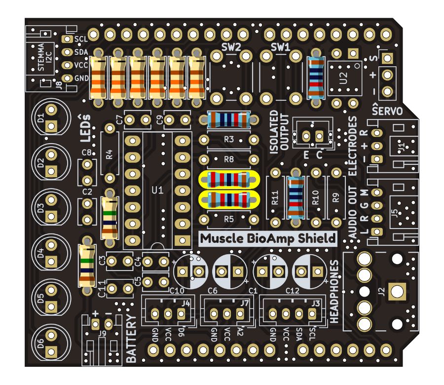
Step 5 - 22K Resistors#
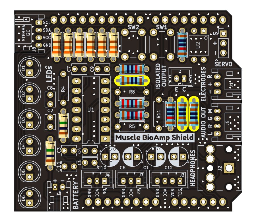
Step 6 - 1K Resistors#
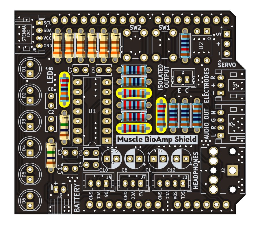
Step 7 - 220K Resistors#
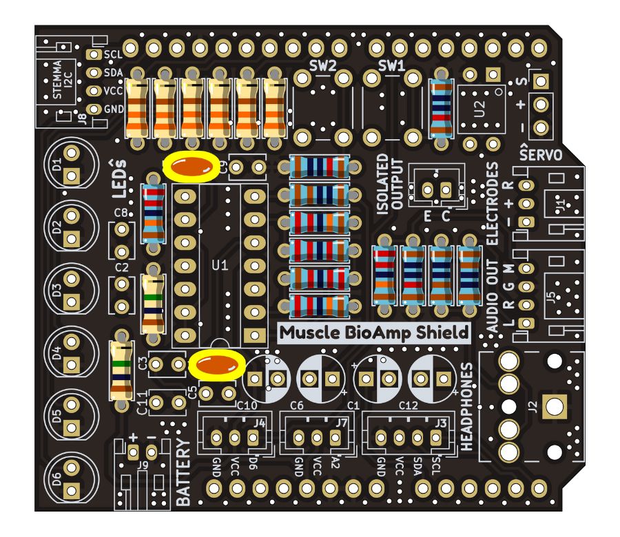
Step 8 - 1nF Capacitors#
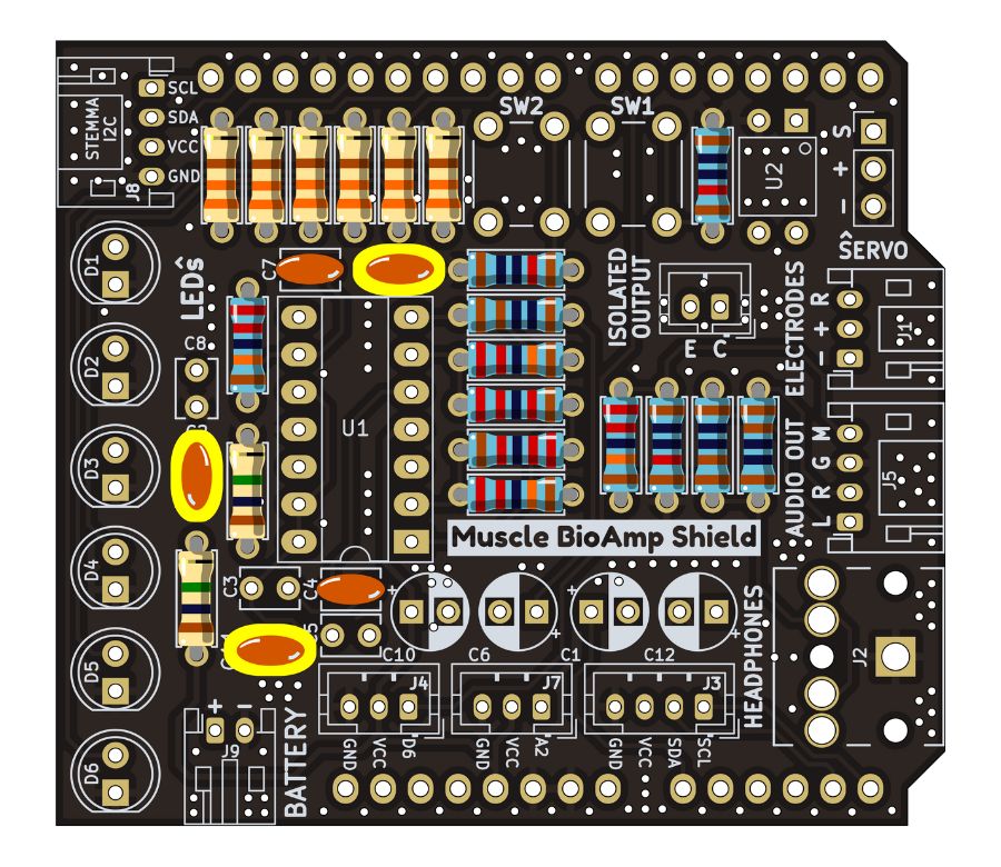
Step 9 - 100nF Capacitors#

Step 10 - 100pF Capacitors#
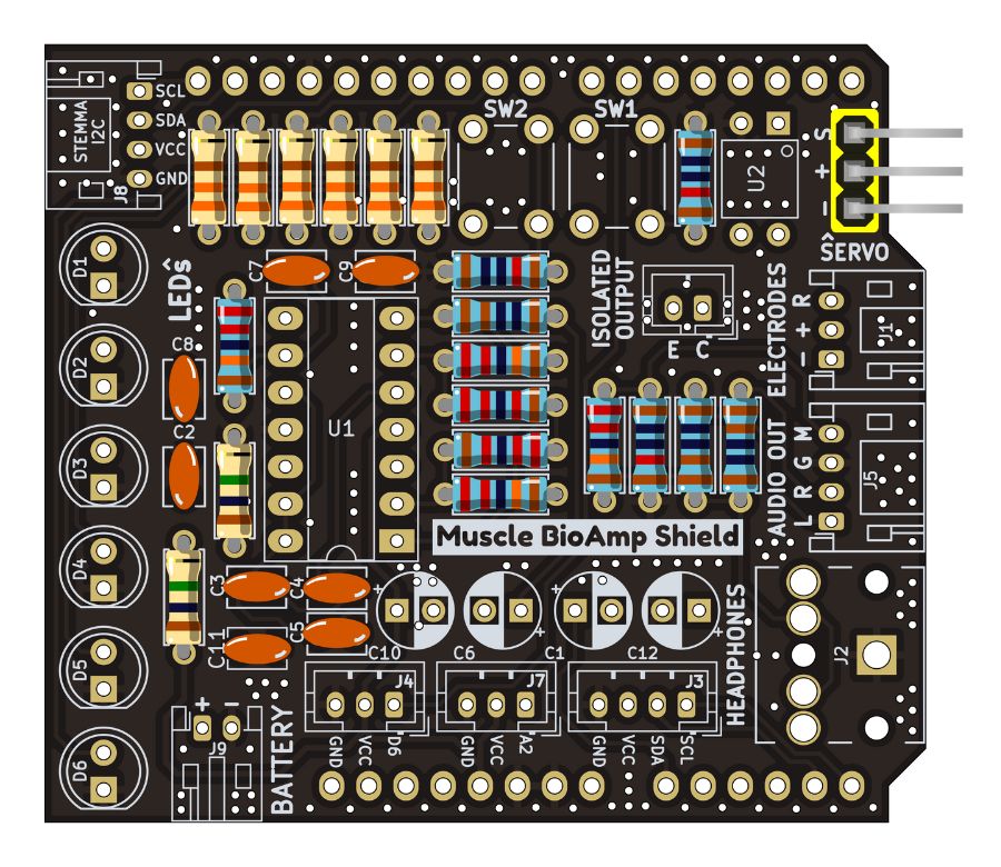
Step 11 - Angled Header Pins#
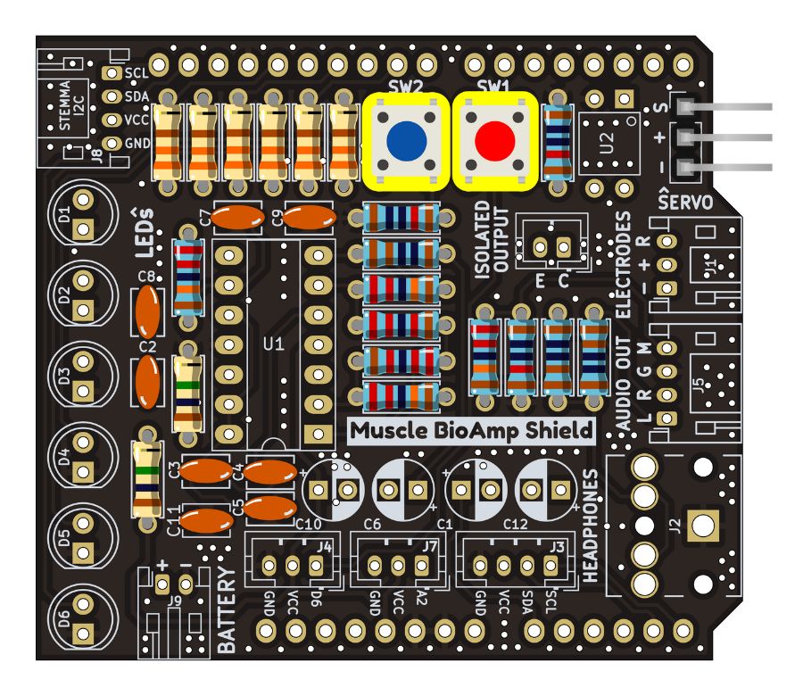
Step 12 - 5x5mm Buttons#
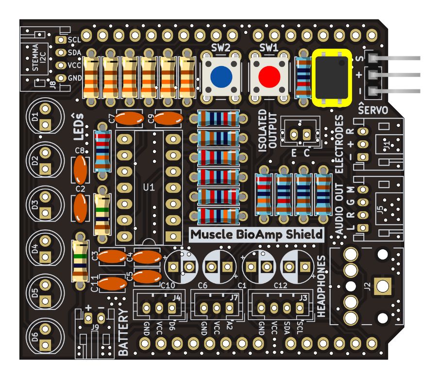
Step 13 - OptoIsolator#
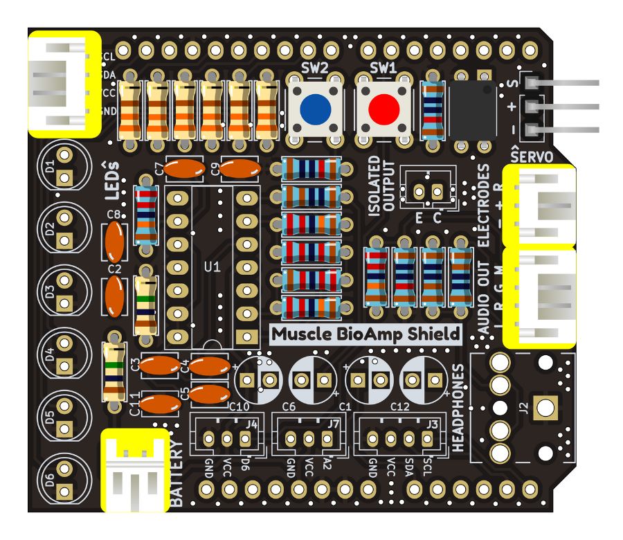
Step 14 - JST PH Angled Connectors#

Step 15 - JST PH Straight Connectors#
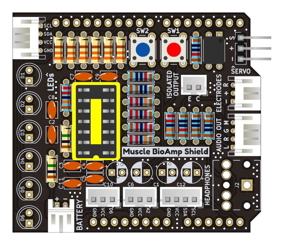
Step 16 - IC Socket#
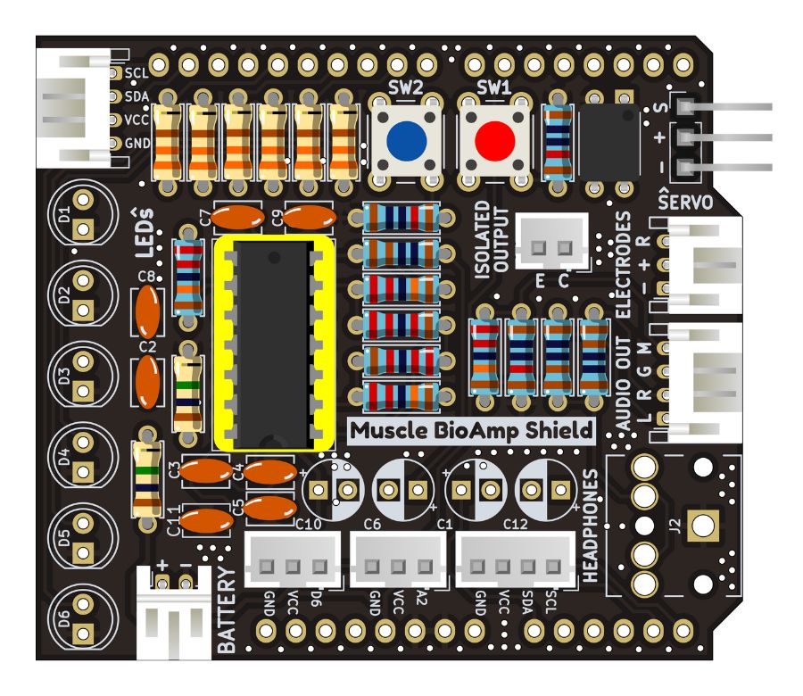
Step 17 - IC#

Step 18 - LEDs#
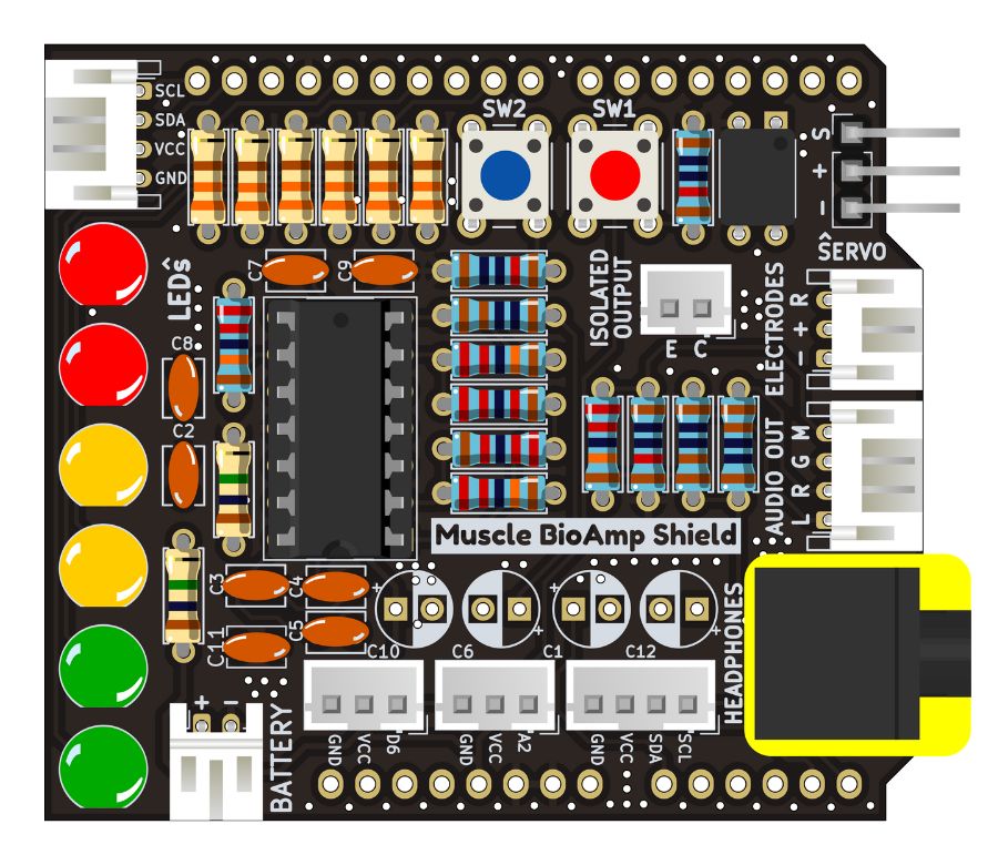
Step 19 - 3.5mm Headphone Jack#
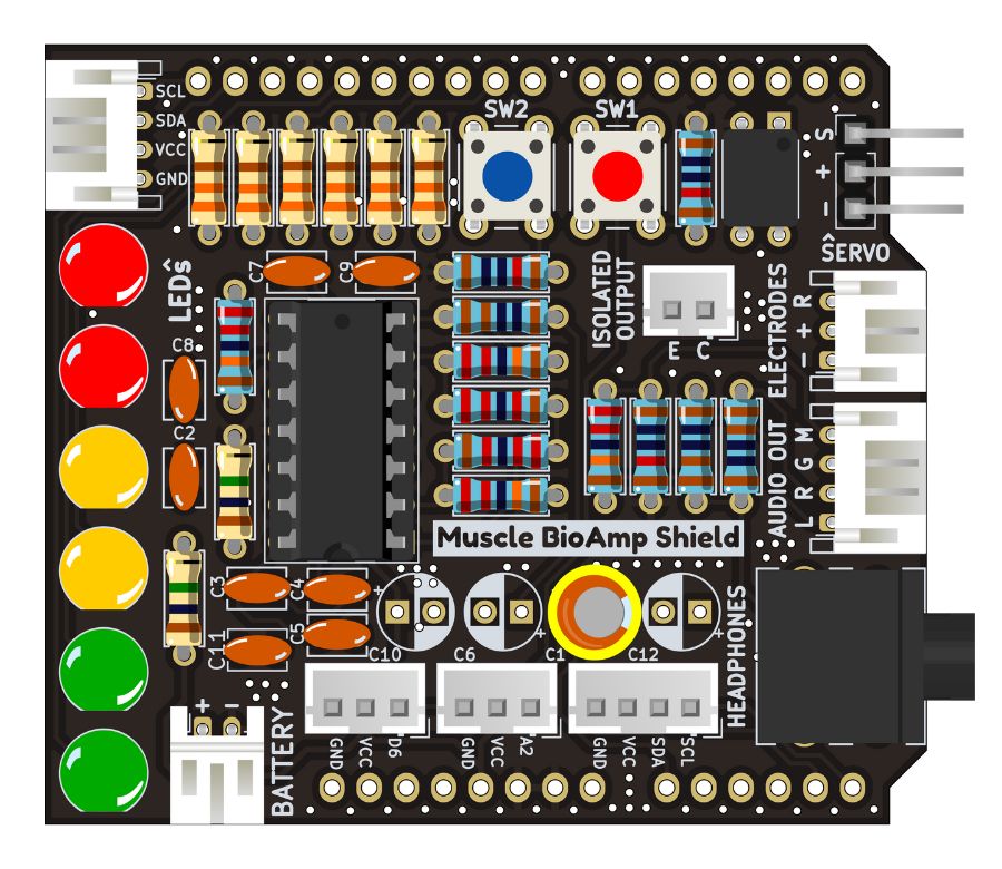
Step 20 - 2.2uF Capacitor#
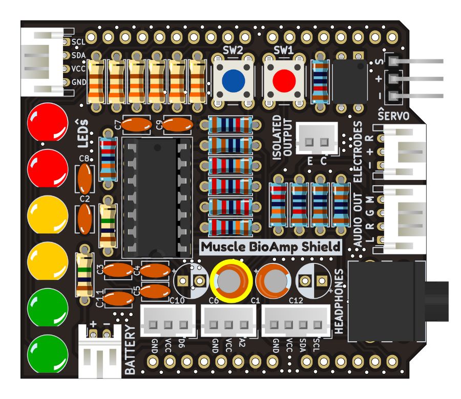
Step 21 - 1uF Capacitor#
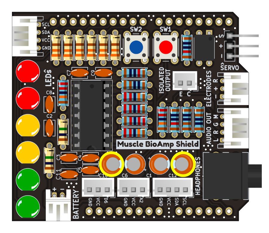
Step 22 - 470uF Capacitor#
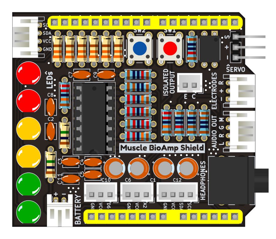
Step 23 - Header Pins#
Step 24 - Assembled Shield#
Still can’t figure out the assembly? You can follow the video provided below to assemble your Shield.
Using the Sensor#
Step 1: Stack on Arduino Uno#
Stack the Muscle BioAmp Shield on top of Arduino Uno properly.
Step 2: Connecting Electrode Cable#
Connect the BioAmp Cable to Muscle BioAmp Shield as shown.
Step 3: Skin Preparation#
Apply Nuprep Skin Preparation Gel on the skin surface where electrodes would be placed to remove dead skin cells and clean the skin from dirt. After rubbing the skin surface thoroughly, clean it with an alcohol wipe or a wet wipe.
For more information, please check out detailed step by step Skin Preparation Guide.
Step 4: Electrode Placements#
We have 2 options to measure the EMG signals, either using the gel electrodes or using dry electrode based Muscle BioAmp Band. You can try both of them one by one.
Using gel electrodes#
Connect the BioAmp cable to gel electrodes,
Peel the plastic backing from electrodes
Place the IN+ and IN- cables on the arm near the ulnar nerve & REF (reference) at the back of your hand as shown in the connection diagram.
Using Muscle BioAmp Band#
Connect the BioAmp cable to Muscle BioAmp Band in a way such that IN+ and IN- are placed on the arm near the ulnar nerve & REF (reference) on the far side of the band.
Now put a small drop of electrode gel between the skin and metallic part of BioAmp cable to get the best results.
Tip
Visit the complete documentation on how to assemble and use the BioAmp Bands or follow the youtube video given below.
Tutorial on how to use the band:
Note
In this demonstration we are recording EMG signals from the ulnar nerve, but you can record EMG from other areas as well (biceps, triceps, legs, jaw etc) as per your project requirements. Just make sure to place the IN+, IN- electrodes on the targeted muscle and REF on a bony part.
Step 5: Connect Arduino UNO to your laptop#
Connect your Arduino UNO to your laptop using the USB cable.
Warning
Make sure your laptop is not connected to a charger and sit 5m away from any AC appliances for best signal acquisition.
Step 6: Uploading the code#
Go to Chords Arduino Firmware github repository, scroll down to see a list of development boards compatible with Chords Software Suite.
Link for the Github repo: Chords Arduino Firmware
If you are using Arduino UNO R3, copy the arduino sketch for your board and paste it in Arduino IDE. Uncomment
#define BOARD_UNO_R3at the start of the code.If you are using Arduino Uno R4 Minima/WiFi, you just have to copy the arduino sketch for the board, paste it in Arduino IDE and upload.
To upload the code, go to
tools>boardand select you board name. If the name doesn’t appear, install the required libraries. In the same menu, select the COM port on which your board is connected. To find out the right COM port, disconnect your board and reopen the menu. The entry that disappears should be the right COM port. Now click on the upload button.
Step 7: Visualise EMG signals on Chords-Web#
Visit chords.upsidedownlabs.tech.
Click on “Visualize now” button.
- At the bottom, you can see buttons to access various applications:
Chords Visualizer: Use this application for real-time data visualization, recording and data management, filter options, and multi-channel support.
Serial Wizard: This interface provides real-time serial data visualization using serial plotter and monitor, optimised data rendering, baud rate selection and options to toggle between different modes.
Click on any of the button according to your requirement, select the COM port and click OK. You will be able to visualize your signals on the screen.
Step 8: Visualise EMG signals on Chords-Python#
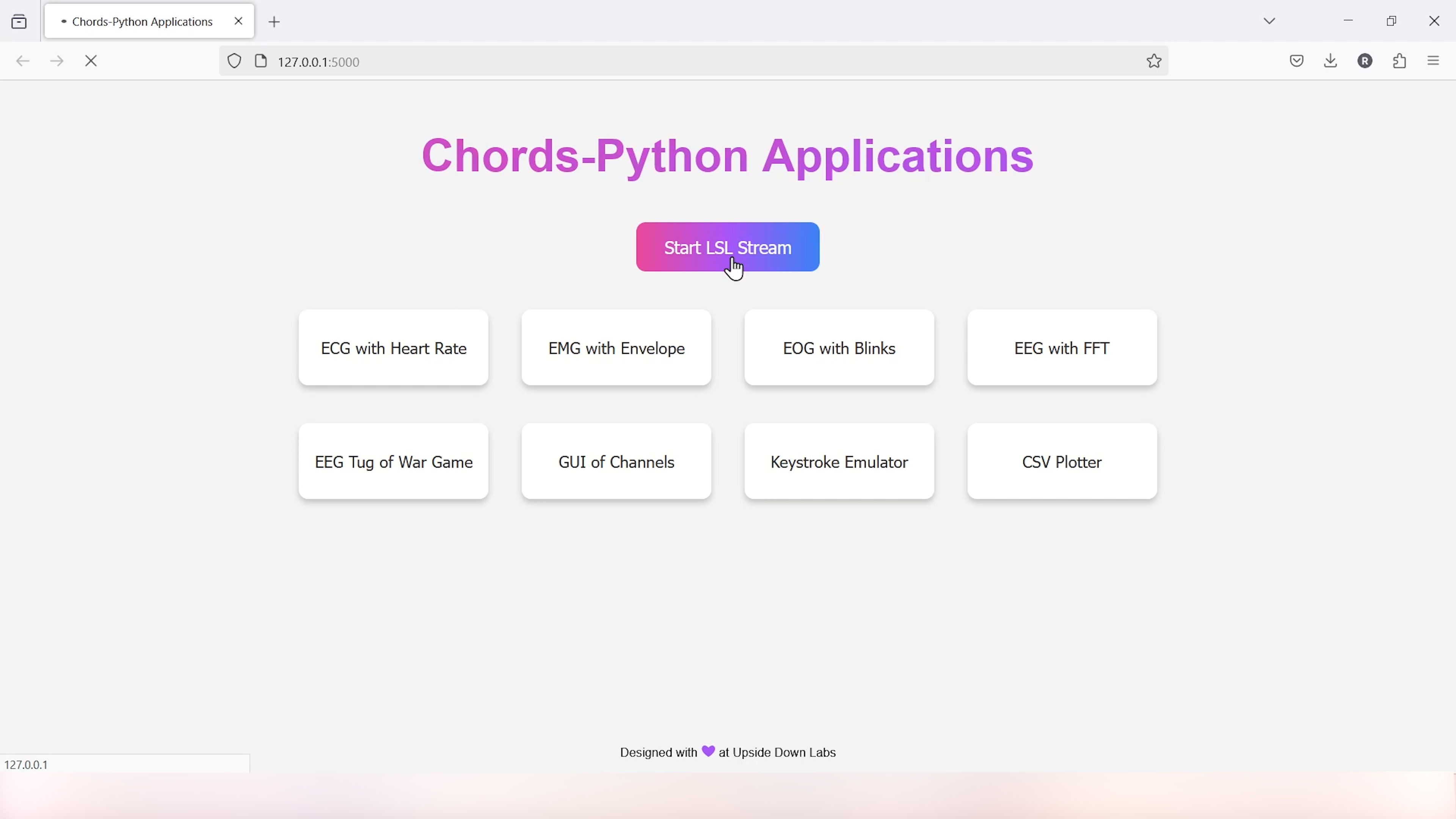
Since you have uploaded the firmware already to your board, use our python script and follow the steps given in the Chords-Python documentation for LSL streaming, CSV data logging, verbose output with detailed statistics and error reporting. Not only that, you get a complete web interface to access various applications (like ECG with heart rate, EMG with envelope, GUI of channels, CSV plotter, etc.) that you can use to further analyse your signals and create HCI/BCI projects.
Step 9: Visualise EMG signals on LEDs#
Copy paste the Arduino Sketch given below in Arduino IDE:
Make sure you have selected the right board and COM port. Now upload the code, and flex your arm. You’ll see the LED bar going up. More strength you apply, more the LED bar goes up.
Step 10: Listen to your EMG signals#
You can either listen to the muscle signals (EMG) on a speaker or wired earphones/headphones. Let’s try both of them.
Listening EMG on speakers#
Connect the BioAmp AUX cable on a bluetooth speaker that have 3.5mm jack support.
Switch on the speaker and turn the volume to maximum.
Flex and listen to your muscles.
Listening EMG on a wired earphones/headphones#
Plug your wired earphones or headphones on the 3.5mm jack of BioAmp v1.5.
Plug it in your ears.
Flex and listen to your muscles.
Step 11: Controlling a servo motor#
Connect the servo claw to Muscle BioAmp Shield.
Copy paste the Arduino Sketch given below in Arduino IDE:
Make sure you have selected the right board and COM port. Now upload the code, and flex your arm to control the servo claw in real time.
Step 12: Controlling a servo claw#
Connect the servo claw to Muscle BioAmp Shield.
Copy paste the Arduino Sketch given below in Arduino IDE:
Make sure you have selected the right board and COM port. Now upload the code, and flex your arm to control the servo claw in real time.
Step 13: Connecting 9V battery#
Till now, the power for the EMG system was coming from the laptop via USB cable of Arduino Uno but there can be 2 ways in which you can make the system portable:
Using 9V battery: Directly connect a 9V battery to Muscle BioAmp Shield using a 9V snap cable.
Using Power Bank: Instead of connecting the USB cable of Arduino Uno to laptop, you can directly connect it to power bank.
Note
Do not use 9V battery while controlling a servo claw using Muscle BioAmp Shield. Instead connect the Arduino UNO to a power bank or directly to your laptop.
Step 14: Other functionalities you can explore#
Using I2C ports#
There are 2 I2C ports available on Muscle BioAmp Shield and you can connect hundreds of devices having I2C compatibility using the 4-pin JST PH 2.0 mm STEMMA cables provided.
Some of the examples are: OLED screens, character displays, temperature sensors, accelerometers, gyroscopes, light sensors, BioAmp Hardware, etc.
Using STEMMA Digital port#
Connect Arduino Uno’s D6 digital I/O pins using STEMMA digital connectors.
Using STEMMA Analog port#
Connect Arduino Uno’s A2 analog input pins using STEMMA analog connectors.